
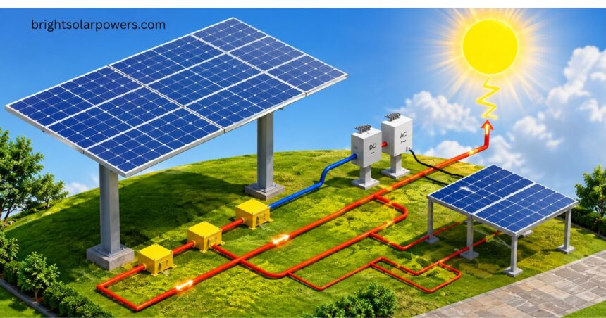
A solar wiring diagram works like a map for your entire solar energy system, showing exactly how power moves from the roof to your home.
I always tell homeowners that a good schematic keeps a residential setup dependable and safe, because every wire and connector has its place. When you look closely, you notice how safety devices, a disconnect switch, and proper wire selection protect the whole build from day one.
Good design starts with understanding the five building blocks of a system: the PV panels, the DC to AC inverter, the wiring run, the fusebox, and the electricity meter.
Each piece plays a role in turning sunlight into usable power, and skipping a step often leads to underperformance down the road.
I have seen installers lean on design software like Aurora to handle stringing and auto-stringing automatically, cutting down on costly mistakes.
A smart wiring configuration balances voltage and current so the inverter connections run smoothly without inverter clipping cutting into output.
Planning ahead for battery storage, energy storage, and future grid-tied upgrades keeps a cost breakdown realistic while boosting system efficiency and long-term energy generation.
Routine maintenance, attention to shading patterns, and awareness of how utility billing handles import and export all add up to a longer inverter lifespan and better overall efficiency.
Wiring Solar Panels in Series
With series wiring, you connect the positive terminal of one panel to the negative terminal of the next, building a simple panel chain across the roof.
This setup raises the total voltage of the array while the current along the current path stays equal to a single panel output, which suits many an inverter voltage requirement.
The catch is that shading or a fault on one module can drag down the string voltage and the entire string output, though bypass diodes help current get around the weak link.
Wiring Solar Panels in Parallel
In parallel wiring, every panel’s positive terminals join a common conductor, and the negative terminals link together the same way. This method adds up the total current while the voltage across the array stays at the single panel voltage, giving each module an independent panel contribution to the system.
Because of this, parallel setups offer strong shade tolerance, though you will need a thicker cable gauge and reliable protective equipment to handle the extra current safely.
Inverters
The inverter is the heart of the system, turning raw DC electricity from the panels into usable AC voltage, often around 240V, for your appliances and the grid.
Good wiring design must respect voltage limits, current limits, and overall system capacity, since a mismatch is often the biggest cost item in a failed grid-tied installation.
Every grid connection setup also needs the right protection devices in place before the system can safely send power outward.
Before choosing an inverter, check its inverter specifications: the maximum DC input voltage, the minimum start voltage, and the maximum input current all matter for safe operation. The number of MPPT channels, formally known as Maximum Power Point Tracker inputs, decides how well the system handles different shading conditions and panel orientation on the same roof.
Getting the string matching right across each of the MPPT channels keeps every string running near its maximum power point.
Beyond the basics, many inverters come with a power monitoring display, wireless remote monitoring, and historical logging so you can track output over time. Tech-savvy owners often like a PC interface or web interface for deeper analysis, along with expandability and modular expansion for adding panels later.
Some setups skip a central inverter altogether and use microinverters, giving each per-panel inverter its own independent output regardless of shade.
Wiring, Cables & Connectors
Every safe system depends on matching the connector rating, voltage rating, current rating, and overall cable rating to the job, since undersized wire raises resistance and hurts efficiency.
Poor connections also open the door to safety hazards from moisture, UV exposure, and long-term temperature exposure out on the roof.
This is why installers reach for proper PV wire or solar cable for every interesting connections run between panels.
MC4 connectors have become the industry standard for joining panel leads, and pairing them with wire management clips or zip ties keeps the wiring neat and protected.
Circuit breakers, fuses, and general overcurrent protection guard the solar wiring diagram system, while a charge controller needs its own dedicated battery cabling when storage is part of the design.
The inverter wiring run down to the main fuse box should include a disconnect switch or isolator switch for safe shutdowns.
Running this wiring is rarely cheap, and the labor cost usually outweighs the material cost because of the effort needed for concealment along walls and rooflines.
A clear shutdown sequence protects anyone working on the array later, since a lethal voltage can still be present even when the panels look powered down, so I always recommend hiring a qualified installer rather than guessing at the steps. Getting these small details right from day one saves real money and real risk over the life of the system.
Reading a Solar Panel Wiring Diagram
Learning to read a wiring diagram is one of the first skills I ever picked up, because this kind of schematic shows every one of the electrical components and their connections at a glance. It traces the electricity flow from the panels toward the power meter, a storage solution, or straight into the electrical grid, depending on how the system is built.
Being able to follow this layout supports better system planning, faster troubleshooting, and easier future upgrades down the line.
Common Symbols Used in Solar Electrical Diagrams
Every wiring drawing uses symbols, and most professionals rely on standard electrical symbols to represent solar panels, inverters, batteries, and charge controllers on the page. These marks can shift slightly from one manufacturer to another or between different design software tools, but the overall system layout usually stays easy to follow.
Alongside the main parts, diagrams also show circuit breakers, isolators, overcurrent devices, utility grid connections, and monitoring equipment so nothing gets left out of the plan.
Understanding Current Flow and Circuit Layouts
A solar system produces direct current, or DC electricity, from the panels, but most homes actually run on alternating current, or AC solar wiring diagram electricity, to power home appliances and connect to the electrical grid. Wiring diagrams show exactly where this conversion happens, which makes the whole current flow easier to picture from start to finish.
Any good installer spends time tracing current through the drawing and checking every component connections point before switching the system on.
Identifying Key System Components
A wiring diagram highlights the handful of parts that make a system work: the solar panels that create DC current, and the inverter that turns it into usable AC current.
Depending on the system design, you might also find charge controllers, batteries, monitoring devices, and protection devices built into solar wiring diagram the layout. Knowing what each part does makes later wiring configuration decisions much easier to get right.
Series-Parallel Systems
Larger installations often combine both approaches through series-parallel wiring, mixing strings to hit the exact voltage requirements and current requirements an inverter needs.
This blended layout shows up often in both residential systems and commercial systems, where multiple strings must work together under one roof.
The final shape depends on system requirements and equipment availability, but the payoff is real flexibility for larger arrays.
Matching Wiring Configuration to Project Requirements
There is no single perfect layout, since system size, cable runs, equipment compatibility, and local shading conditions all shape the best wiring layout for a project. Homeowners with future expansion plans need a design that leaves room to grow, while also meeting today’s performance needs and system objectives.
This decision also decides which inverters, charge controllers, connectors, and protection devices end up on the final parts list.
DC Isolators
DC isolators let you safely disconnect part of the array whenever maintenance, inspection, or emergency conditions call for it. Getting the cable sizing and cable routing right alongside this isolation equipment cuts down on energy losses across the whole run. Small choices like these add up to real long-term reliability for the entire solar wiring diagram.
Charge Controllers and Battery Interfaces
Adding battery storage brings a few new parts into the mix, starting with charge controllers and battery interfaces that manage how power moves in and out
Choosing the right components for actual energy requirements protects long-term battery health just as much as it protects performance.
Grid-Tied Wiring Diagrams
A grid-tied wiring diagram shows how solar panels, inverters, protection devices, and utility grid connections all link together in one grid-connected installation.
The setup turns sunlight into usable power for the home first, and any excess generation can then export out to the grid. Whether that export is allowed depends on local grid configuration rules and local regulations, which is part of why this layout is prized for its simplicity.
Solar-Plus-Battery Storage Wiring Diagrams
Diagrams for battery-backed homes add more detail, showing solar arrays, solar isolators, solar inverters, consumer units, and the same utility grid connections seen in simpler setups. They also map out battery connectivity, energy control systems, and communication networks that keep generation, storage, and household use working together.’
Reviewing this kind of layout closely supports smooth usage coordination and confirms standards compliance with local electrical codes.
Planning for Future Expansion
Smart installation planning always leaves room for future expansion, whether that means more storage capacity, higher electricity loads, solar wiring diagram or new smart energy solutions later on. Building this flexibility in from day one means you can grow the system without a full redesign down the road.
Managing Energy Flow
As systems grow more advanced, energy flow can shift between the solar panels, battery storage, household loads, and the grid depending on the moment. This routing responds to changing electricity system conditions and personal user preferences, which is part of what makes modern setups feel so responsive.
Planning ahead for future energy requirements makes later integration of new smart energy solutions far simpler.
Optimizing with Storage & Energy Management Tech
Modern storage technologies and energy management technologies have turned basic solar setups into something closer to a truly responsive energy system.
More households now aim to boost their self-consumption and overall energy efficiency, which is why current solar panel wiring diagrams so often include battery storage systems and full energy management infrastructure by default. The result is a genuinely flexible energy system that adapts as needs change.
Residential Battery Storage Integration
A good example of this is the EcoFlow PowerOcean Single-Phase, a battery storage system built for residential solar storage that stores extra daytime power for later use.
Its scalable design lets homeowners add capacity as their energy needs grow, supporting stronger self-consumption over time. From what I have seen with similar setups, this kind of unit fits neatly into longer long-term energy planning.
Coordinating Use via Smart Energy Management
The EcoFlow Intelligent HEMS brings energy monitoring and scheduling capabilities into the picture, coordinating solar energy generation, energy storage, and household consumption in real time.
This kind of tool helps families make more informed energy decisions about when to run appliances or draw from storage. The end goal is always the same: stronger self-consumption and less power wasted along the way.
Voltage, Current, Power
Voltage, measured in volts and written as V, describes the electrical charge difference between two points, and this difference is what pushes current to move. Current, or I, measured in amps, describes the actual current flow, while power, or P, measured in watts, equals voltage times current and represents stored potential energy being put to work.
More sunlight, or irradiance, raises panel voltage, while rising temperature lowers it, a relationship covered by temperature coefficients.
The inverter doesn’t just turn DC power into AC power; it also constantly hunts for the sweet spot on the panel’s output curve, a method called maximum power point tracking, run through the MPPT.
Engineers study this behavior using IV curves and power-voltage curves, which show exactly where output peaks under different conditions. Understanding these basics makes every other wiring decision in this guide much easier to follow.

Sequence of Operations Info Needed Before Stringing
Before stringing panels together, you need the full set of inverter specifications: the maximum DC input voltage, the minimum start voltage, the maximum input current, and the MPPT count the unit supports.
On the panel side, check the open circuit voltage, or Voc, and the short circuit current, or Isc, both measured under Standard Test Conditions, or STC.
Those STC numbers assume 1000W per square meter of sunlight at 25 degrees Celsius, or 77 degrees Fahrenheit, so a proper temperature adjustment is always needed to match true real-world conditions.
Basic Rules for Wiring Solar Panels
Keeping a string within the inverter voltage range and under the maximum current limit, while staying above the minimum start voltage, is the first rule of safe wiring.
Local code requirements matter too, since the National Electrical Code in the United States generally caps residential voltage at 600V, while Europe allows higher voltages for residential systems.
Relying only on basic STC values can be misleading, so proper temperature-adjusted calculations using the right formula give a truer picture of real string length.
Tools like Aurora software handle this math automatically, checking whether a proposed string length actually fits the inverter’s range once temperature is factored in.
Strings feeding the same MPPT ports should also share similar azimuth, orientation, tilt, and irradiance, since mismatches between strings lead to solar wiring diagram real efficiency loss and power output loss. A well-known case in Cathedral City California showed how ignoring shade can leave a system stuck as an underperforming system.
In that project, poor planning around shade impact repeatedly pushed the array below its working range, triggering a start voltage failure that cut daily output far below projections.
It is a clear reminder that these basic rules protect real money, not just paperwork. Getting them right the first time avoids a costly redesign later.
Advanced Design Considerations
Some designers deliberately try oversizing array capacity, pushing the theoretical maximum voltage just above the inverter’s limit to squeeze out extra production gains.
This choice accepts some clipped production during peak sun hours as a fair trade, a practice known as inverter clipping. Balancing energy solar wiring diagram production maximization with cost minimization is really the goal behind every one of these advanced calls.
Options like module-level power electronics, or MLPE, along with microinverters and DC optimizers, give designers even more control over each panel’s output. Good software tools support this level of design efficiency, modeling different setups before anything gets installed.
These choices rarely have one right answer, but they always come down to matching equipment to the specific roof.
PV Panels as System Cost Driver
PV panels usually make up around 60% of the total system cost, since they generate the raw power that everything else depends on.
That output starts as low voltage direct current electricity, which then travels through high current cables on its way to the inverter. Knowing this cost split helps homeowners budget realistically before a single panel goes on the roof.
Main Fusebox Connection
Most homes can connect straight into their existing wiring without swapping the fuse box, since only a genuinely old fusebox or an unusually small fuse box needs replacing.
This connection lets solar power flow into the house wiring, out to the grid, and past the meter cleanly. Be careful of any quote offered without a proper inspection, since skipping that step is a common shortcut that leads to surprises later.
New Electricity Meter
A new electricity meter is needed to track both import and export, and the electric utility company usually handles this installation at no extra hassle.
Some utilities use this moment to shift customers onto a time of use tariff, so it pays to understand your new electricity tariff before signing anything.
Running appliances with a bit of intelligent usage solar wiring diagram around peak hours can turn this pricing structure into real bill reduction over time.
FAQS about solar wiring diagram
How to do solar wiring?
Connect solar panels in series or parallel to a charge controller, then link to the battery and inverter. Use proper MC4 connectors, correctly sized cables, and a fuse for safe power flow.
How does solar wiring work?
Sunlight hits the solar panel, generating DC electricity that flows to the charge controller and battery. The inverter then converts this DC power into AC electricity for home use.
How to wire a 12V solar system?
Connect a 12V solar panel to a 12V charge controller, then to a 12V battery using rated cables. Add an inverter for AC output and a fuse for short-circuit protection.
How to draw a solar wiring diagram?
Place the solar panel symbol and connect it to the charge controller, battery, and inverter in order. Label the wire gauge, polarity, and safety components so the circuit stays easy to follow.
